- 您现在的位置:买卖IC网 > Sheet目录530 > UPC8182TB-E3-A (CEL)IC MMIC AMP 6-SUPER MINIMOLD
�� �
�
�?� PC8182TB�
�NOTES� ON� CORRECT� USE�
�(1)� Observe� precautions� for� handling� because� of� electro-static� sensitive� devices.�
�(2)� Form� a� ground� pattern� as� widely� as� possible� to� minimize� ground� impedance� (to� prevent� undesired�
�oscillation).�
�All� the� ground� pins� must� be� connected� together� with� wide� ground� pattern� to� decrease� impedance� difference.�
�(3)� The� bypass� capacitor� should� be� attached� to� the� V� CC� pin.�
�(4)� The� inductor� must� be� attached� between� V� CC� and� output� pins.� The� inductance� value� should� be� determined� in�
�accordance� with� desired� frequency.�
�(5)� The� DC� cut� capacitor� must� be� attached� to� input� and� output� pin.�
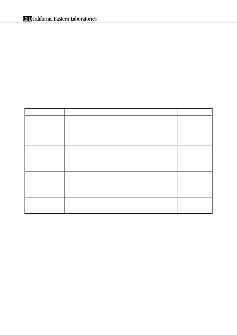
�RECOMMENDED� SOLDERING� CONDITIONS�
�This� product� should� be� soldered� and� mounted� under� the� following� recommended� conditions.�
�methods� and� conditions� other� than� those� recommended� below,� contact� your� nearby� sales� office.�
�For� soldering�
�Soldering� Method�
�Soldering� Conditions�
�Condition� Symbol�
�Infrared� Reflow�
�VPS�
�Wave� Soldering�
�Partial� Heating�
�Peak� temperature� (package� surface� temperature)�
�Time� at� peak� temperature�
�Time� at� temperature� of� 220� ?� C� or� higher�
�Preheating� time� at� 120� to� 180� ?� C�
�Maximum� number� of� reflow� processes�
�Maximum� chlorine� content� of� rosin� flux� (%� mass)�
�Peak� temperature� (package� surface� temperature)�
�Time� at� temperature� of� 200� ?� C� or� higher�
�Preheating� time� at� 120� to� 150� ?� C�
�Maximum� number� of� reflow� processes�
�Maximum� chlorine� content� of� rosin� flux� (%� mass)�
�Peak� temperature� (molten� solder� temperature)�
�Time� at� peak� temperature�
�Preheating� temperature� (package� surface� temperature)�
�Maximum� number� of� flow� processes�
�Maximum� chlorine� content� of� rosin� flux� (%� mass)�
�Peak� temperature� (pin� temperature)�
�Soldering� time� (per� side� of� device)�
�Maximum� chlorine� content� of� rosin� flux� (%� mass)�
�:� 260� ?� C� or� below�
�:� 10� seconds� or� less�
�:� 60� seconds� or� less�
�:� 120� ?� 30� seconds�
�:� 3� times�
�:� 0.2%(Wt.)� or� below�
�:� 215� ?� C� or� below�
�:� 25� to� 40� seconds�
�:� 30� to� 60� seconds�
�:� 3� times�
�:� 0.2%(Wt.)� or� below�
�:� 260� ?� C� or� below�
�:� 10� seconds� or� less�
�:� 120� ?� C� or� below�
�:� 1� time�
�:� 0.2%(Wt.)� or� below�
�:� 350� ?� C� or� below�
�:� 3� seconds� or� less�
�:� 0.2%(Wt.)� or� below�
�IR260�
�VP215�
�WS260�
�HS350�
�Caution� Do� not� use� different� soldering� methods� together� (except� for� partial� heating).�
�Data� Sheet� PU10206EJ01V0DS�
�15�
�发布紧急采购,3分钟左右您将得到回复。
相关PDF资料
UPC8187TB-EV24
EVAL BOARD UPC8187TB 2.4GHZ
UPC8190K-EVAL
EVAL BOARD FOR UPC8190K
UPC8191K-E1-A
IC I/Q MODULATOR AGC 20-QFN
UPC8194K-EVAL
EVAL BOARD FOR UPC8194K
UPC8195K-E1-A
IC I/Q MODULATOR AGC 20-QFN
UPC8204TK-EV24
EVAL BOARD UPC8204TK 2.4GHZ
UPC8211TK-EV24
EVAL BOARD UPC8211TK 2.4GHZ
UPC8215TU-A
IC AMP LOW NOISE 8-MINIMOLD
相关代理商/技术参数
UPC8182TB-E3-AZ
制造商:NEC 制造商全称:NEC 功能描述:3 V, 2.9 GHz SILICON MMIC MEDIUM OUTPUT POWER AMPLIFIER FOR MOBILE COMMUNICATIONS
UPC8182TB-EVAL
功能描述:放大器 IC 开发工具 For UPC8182TB-A RoHS:否 制造商:International Rectifier 产品:Demonstration Boards 类型:Power Amplifiers 工具用于评估:IR4302 工作电源电压:13 V to 23 V
UPC8186K-E1
制造商:未知厂家 制造商全称:未知厂家 功能描述:RF MODULATOR|BIPOLAR|LLCC|24PIN|PLASTIC
UPC8187TB
功能描述:上下转换器 RFIC Freq Upconvertr RoHS:否 制造商:Texas Instruments 产品:Down Converters 射频:52 MHz to 78 MHz 中频:300 MHz LO频率: 功率增益: P1dB: 工作电源电压:1.8 V, 3.3 V 工作电源电流:120 mA 最大功率耗散:1 W 最大工作温度:+ 85 C 安装风格:SMD/SMT 封装 / 箱体:PQFP-128
UPC8187TB-A
功能描述:上下转换器 RFIC Freq Upconvertr RoHS:否 制造商:Texas Instruments 产品:Down Converters 射频:52 MHz to 78 MHz 中频:300 MHz LO频率: 功率增益: P1dB: 工作电源电压:1.8 V, 3.3 V 工作电源电流:120 mA 最大功率耗散:1 W 最大工作温度:+ 85 C 安装风格:SMD/SMT 封装 / 箱体:PQFP-128
UPC8187TB-E3
制造商:California Eastern Laboratories (CEL) 功能描述:Frequency Up-Converter For Wireless Transceiver 6-Pin SOT-363 T/R
UPC8187TB-E3-A
功能描述:上下转换器 RFIC Freq Upconvertr RoHS:否 制造商:Texas Instruments 产品:Down Converters 射频:52 MHz to 78 MHz 中频:300 MHz LO频率: 功率增益: P1dB: 工作电源电压:1.8 V, 3.3 V 工作电源电流:120 mA 最大功率耗散:1 W 最大工作温度:+ 85 C 安装风格:SMD/SMT 封装 / 箱体:PQFP-128
UPC8187TB-EV08
功能描述:射频开发工具 for UPC8187TB-A at 800 MHz RoHS:否 制造商:Taiyo Yuden 产品:Wireless Modules 类型:Wireless Audio 工具用于评估:WYSAAVDX7 频率: 工作电源电压:3.4 V to 5.5 V